
There are several Bosch IP cameras: in general you can search for a specific model from Security and Safety Systems North America (or Security and Safety Systems Italy if you live in my country) where there is a link product selector) thet allows you also to compare different models. You can find a list of all Bosch camera in this Bosch page site, Security and Safety Systems Italy – Sistemi video or in some national vendors like this Italian one.
I tested the camera NBE-5503-AL Bullet 5MP HDR 2,7-12mm auto IP67 IK10 / NBE-5503-AL DINION IP 5000i IR and, in the following you can find some information that can be useful to better know how it works and how it can be configured. Its data sheet can be downloaded here: DINION IP 5000i Data sheet.
You can buy it even from Amazon and have it at home in a few days!
The specification of the Video Surveillance Devices and Sensors Bosch DINION IP 5000i IR can be found in Dinion IP Cameras – Bosch Security Systems where you can find the features of the NBE-5503-AL DINION IP 5000i IR remote devices too.
 In the NBE-5503-AL Bullet 5MP HDR 2.7-12mm auto IP67 IK10 product page, you can find documents and SW: even though the name of the model is a bit different (possibly because it is the US site) this is the only site where I was able to find specific information on that product. In particular, you can find here, in the SW tab, the latest firmware update (it was ver. 6.43.0027 and at 29/5/2019 it is 6.61.0025) that it is better you install if, as it was in my case, the one available on the camera was an old one: the update procedure can be done, for example, using the Configuration Manager application [it was ver. 5.54.0133 but at 29/5/2019, in that product page, it is 6.10.0131 … but going to the downloadstore.boschsecurity site you can find the 6.20.0102 one!]. Note that you better have the newest version of the Configuration Manager with the newest version of the firmare of the camera. For exampe if you have the CPP7.3_FW_7.50.0079.fw firmware version installed on the camera, with an older version of the Configuration Manager the events configuration section shows only a link to the web version of this tool.
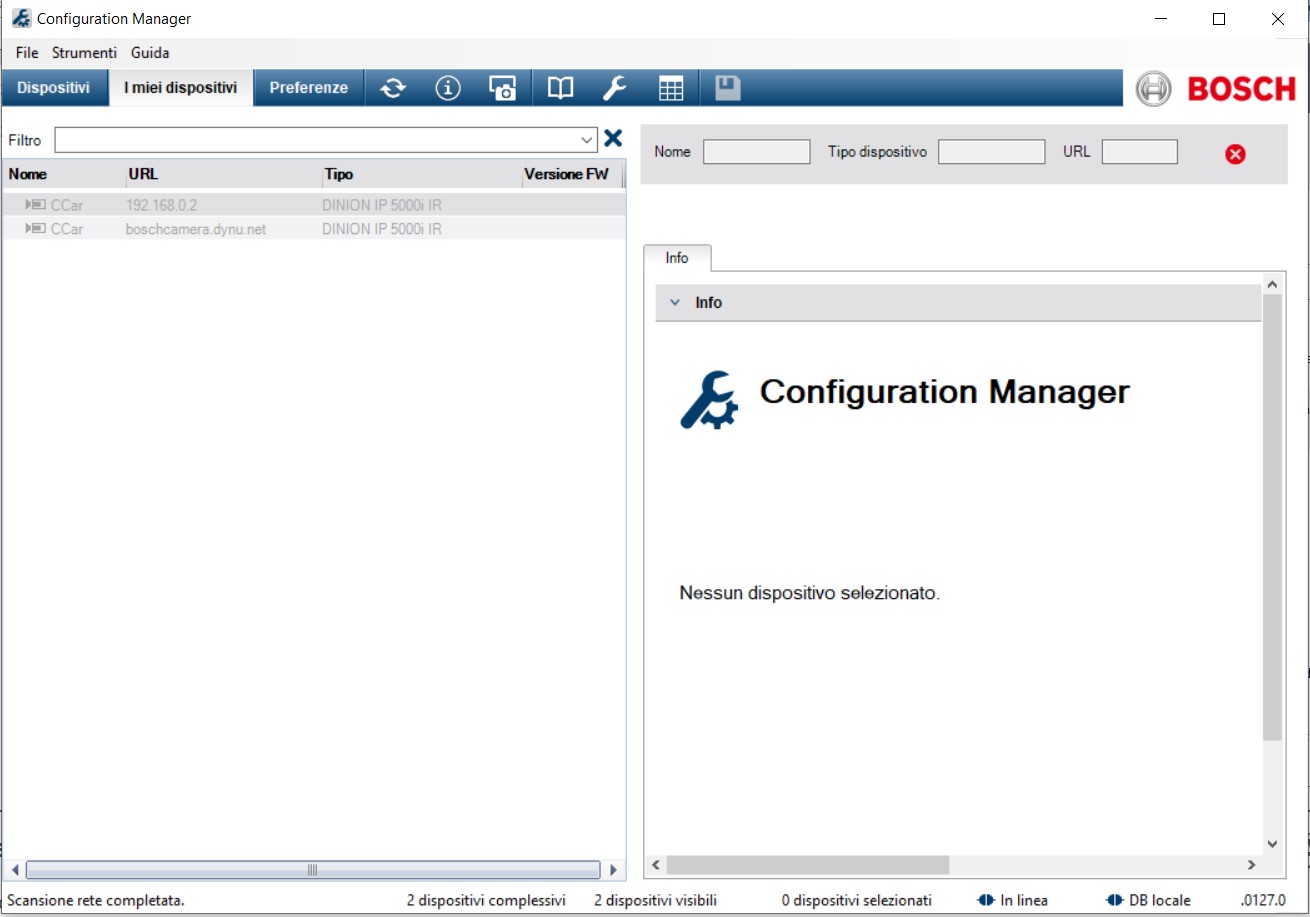
To let the camera be seen and configured with the Configuration Manager, you have to connect both the camera and the PC to the same network (e.g. to the same router). Launching that SW, in the first Devices section there will be listed all the camera found on that network with the related IP address they had been assigned (e.g. 192.168.1.2).
The firmware installation could fail with an error possibly because it does not fit with the specific model/year or other reasons. You can then even try to install using the web interface using the camera current IP (e.g. http://192.168.1.2/upload.htm) instead of the Configuration Manager: with this method at least you can get a more descriptive error message [e.g. Firmware upload error: CHECK_DEVICE(13) invalid target 0x0116 (my trg 0x0110 or 0x0111)] . The reason of this error was unknown to me before I asked to the technical Bosch support by email. Their answer was: “In that case, you needs to update first to 6.50 and then go the version that you wants“. However, where I could find that firmware version 6.50? In the product page there are only 6.61.0025 and 6.60.0065 versions downloadable … and I got the same error trying to install both. Therefore they give me this proper link where there are ALL the Bosch products FW and SW, even the very old one. Here I found not only the 6.50 version to be installed first, but also really newer 7.10.0074 one [P.S. 9/11/2019 CPP7.3_FW_7.50.0079.fw] to be installed next (while on the product site it is only available the link to download the 6.61.0025 one!): therefore much better to check for updates on that different site!!

Bosch site where you can find ALL Bosch products FW and SW
So in this way I succeeded to install both of them in sequence … 🙂
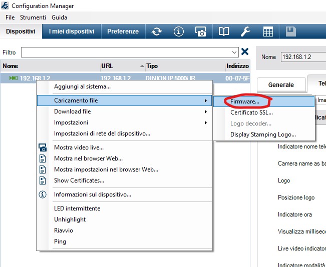
Firmware update from the Configuration Manager (1)

Firmware update from the Configuration Manager (2) – error
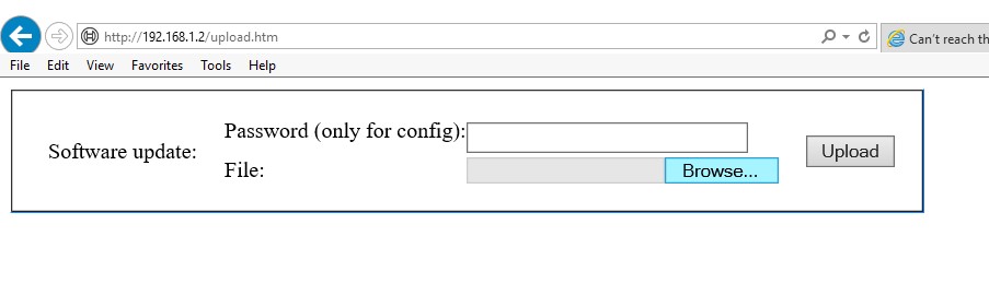
Firmware update from the web interface
Firmware update from the web interface (1)

Firmware update from the web interface (2)

Firmware update from the web interface (3) – error
In the following you can get some useful documents related to that camera: strangely, some of them I found searching in Internet, have a more recent version respect those available from that product page, … so they should be more updated.
Related to the Camera browsing interface:
- Camera Browser Interface (Dinion & Flexidome IP 4000i, 5000i, 6000i cameras (IT) (2017)
- Camera Browser Interface NAI-90022 (2003)
The useful SW, you should download, is the following in the Bosch download area:
- Configuration Manager [it was ver. C5.54.0133 and now 6.10.0131]
- Video Client [it was ver. 1.7.6.078 and now it is 1.7.6.079]
- Video Security Client (more cameras control) [ver 2.2.1.43]
- MPEG-ActiveX
Note that, even though you can see the camera stream and interact with it from any browser, once you know its IP address (e.g. https://192.168.1.2/view.htm?mode=l that can be found also on the top right of the Configuration Manager application when the camera is discovered on the same subnetwork, the better way of interaction is using the Configuration Manager you can download from the Bosch Security Systems DownloadStore.
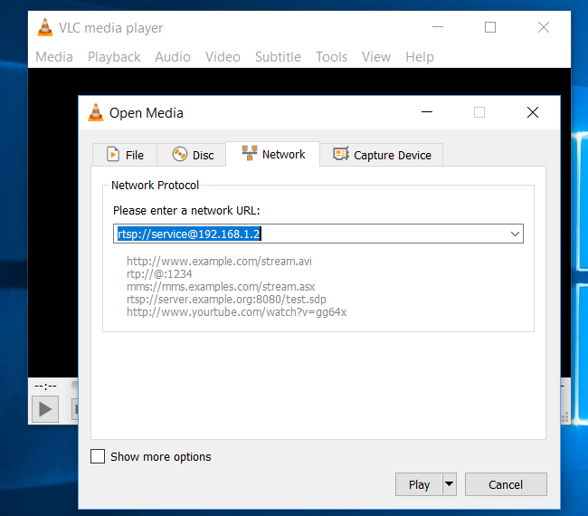
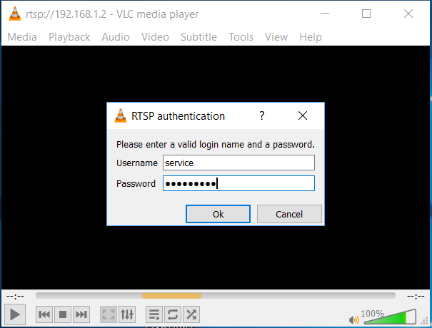
Once you know the IP address of the camera, you could even use what ever SW that allows to get a video stream, like VLC, as you can see from the following screenshots. Note that the protocol to be used for the communication of the camera stream is rtsp, so the URL to set should be, for example rtsp://service@192.168.1.2 if you want to login with a username service: a window asking for his password will popup, before you can get the camera stream in VLC. However, the video delay will be much greater than the one you experiment with the Bosch Configuration Manager client: therefore it is better to use this last one client.
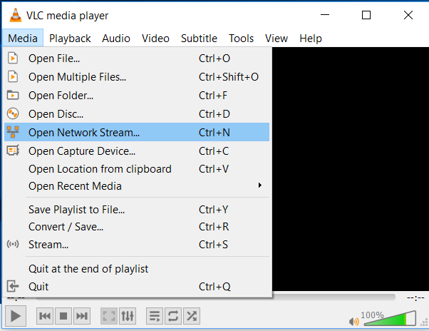
Using a general purpose network media player (e.g. VLC) to see the camera stream (1)
Using a general purpose network media player (e.g. VLC) to see the camera stream (2)
Using a general purpose network media player (e.g. VLC) to see the camera stream (3)
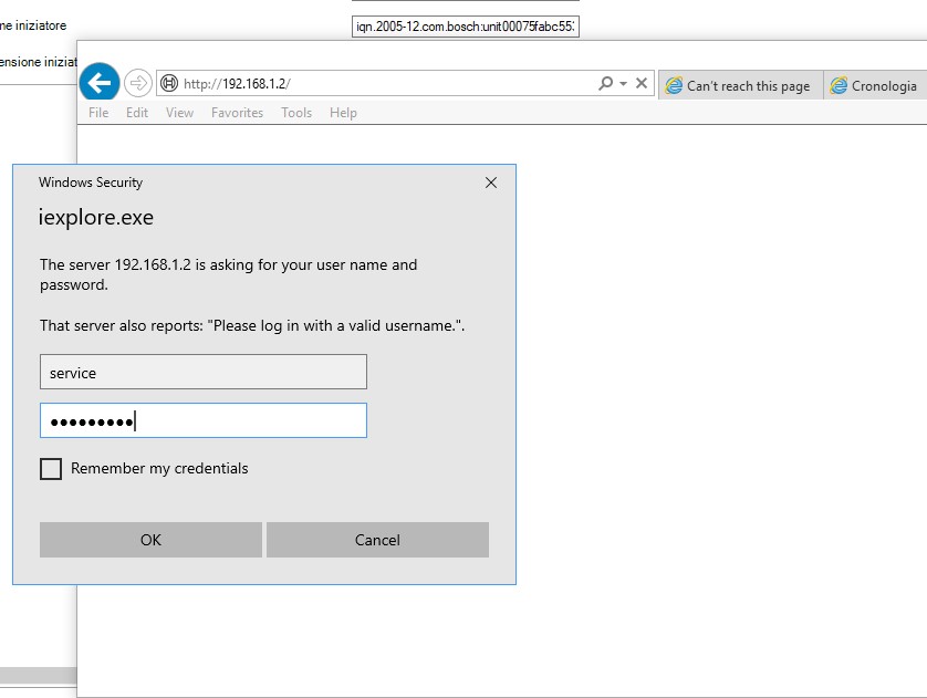
If you want to test the sending of an email when an alarm happens, you can properly configure it from the of the Configuration Manager, after having authenticated the user to access to the camera.
There are three types of user roles, the service, the user and live: only users of the first group can manage the camera configuration settings.
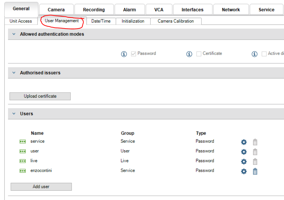
User management

User authentication to access the specific camera
Configuring VCA, first of all you have to possibly mask irrelevant areas, in order to limit processing and also to prevent false alarms.
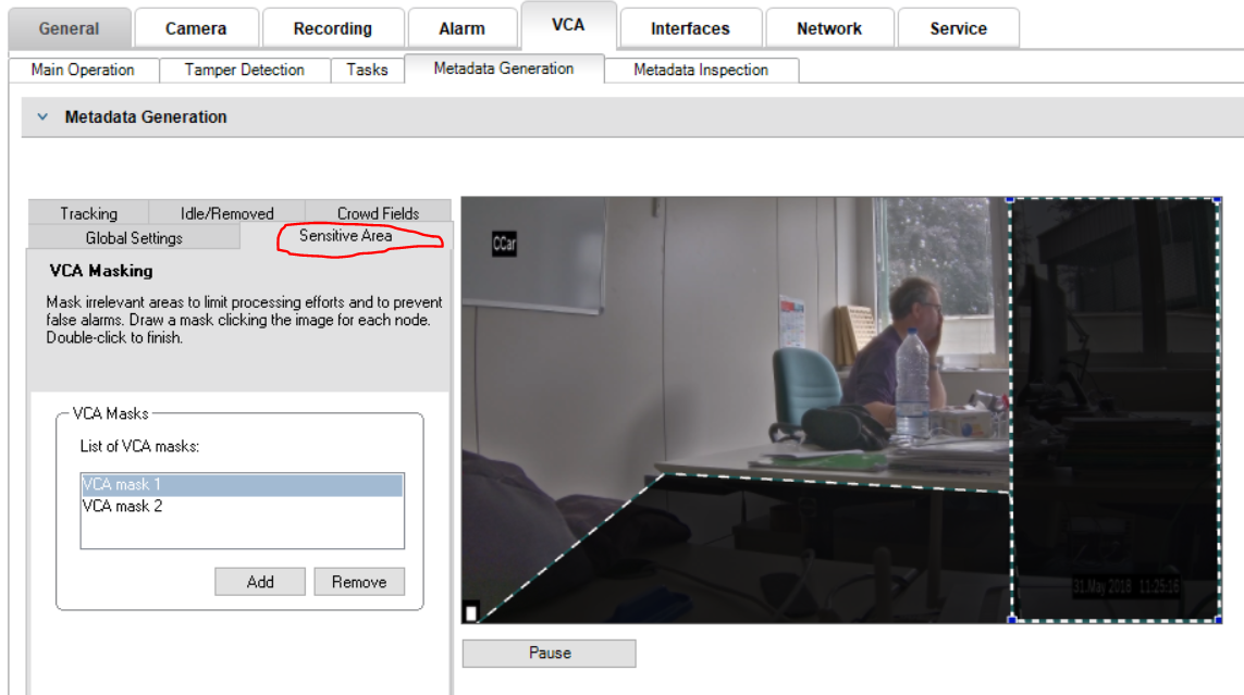
Set Sensitive Areas for VCA Masking
Moreover, this time in the Camera tab section, you can possibly set one or more Privacy Masks each one with 4 nodes by default (only one more node can be added right clicking on one of its lines): you have to check the combo enabled to let that mask be active and so displayed (with the chosen color) also in the Tasks sub-tab of the VCA tab.
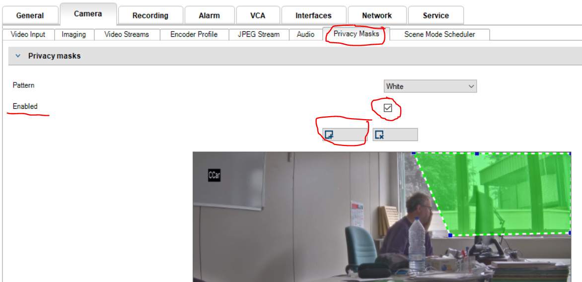
Privacy Masks setting
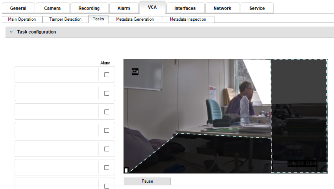
VCA Task tab definition with both Privacy Mask and Sensitive Areas set
As stated in chapter Limitations Intelligent and Essential Video Analytics of the SW manual Video Content VCA 6.30, is required both a camera calibration for object classification and one of the two 3D tracking modes must be selected.
The camera calibration is essential to make the VCA recognition work properly! (see chapter 9.2.1 of manual Video Content VCA 6.30).
The Camera Calibration requires to set the Positioning (e.g. the height; the focal length is set by the camera sensor itself) and in the Sketch Calibration tab it is possible to draw parallel/perpendicular lines and angles of 90 degree to set a better calibration.
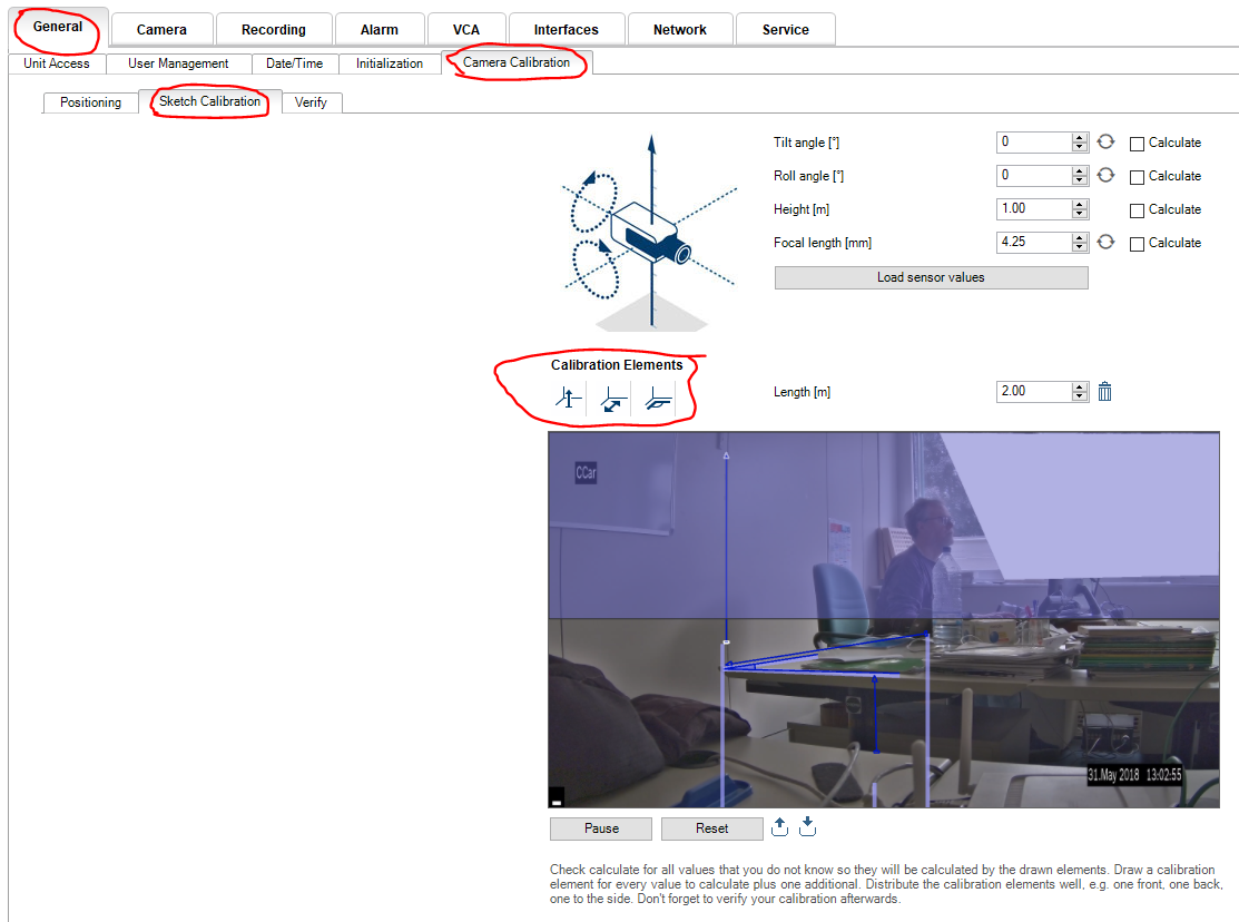
Camera calibration
It is convenient to let the calculation of Tilt angle, Roll angle and Focal length be done automatically, setting the associated Calculate checkbox and then click on the refresh two arrows icon. In order that the automatic calibration is properly done, it is very useful to set both “vertical” and “on the ground” arrows, both near and far from the camera, and specify for each the length in meters. If angles are drawn, by default 90 degree is set but, if needed, that value can be changed.
The only value that must be set by hand is the Height of the camera. Note that, as suggested, the camera is positioned at a height of 3 meter or more, possibly the horizon line is not visible if the surveilled area is sufficiently closed to the camera.
There is also a Verify section where you can check if the height of objects in the scene are the right one (e.g. let one guy move near and far from the camera and check that his height is the right one wherever he is).
If the camera is calibrated, a proper indication is shown in the VCA -> Metadata Generation -> Global Settings tab.

Camera is calibrated advice
In order to possibly identify, in a Task definition, upright persons, bikes, cars or trucks, you have to set properly the VCA -> Metadata Generator -> Tracking tab section (i.e. 3D tracking or 3D people tracking if you are interested only in people identification).
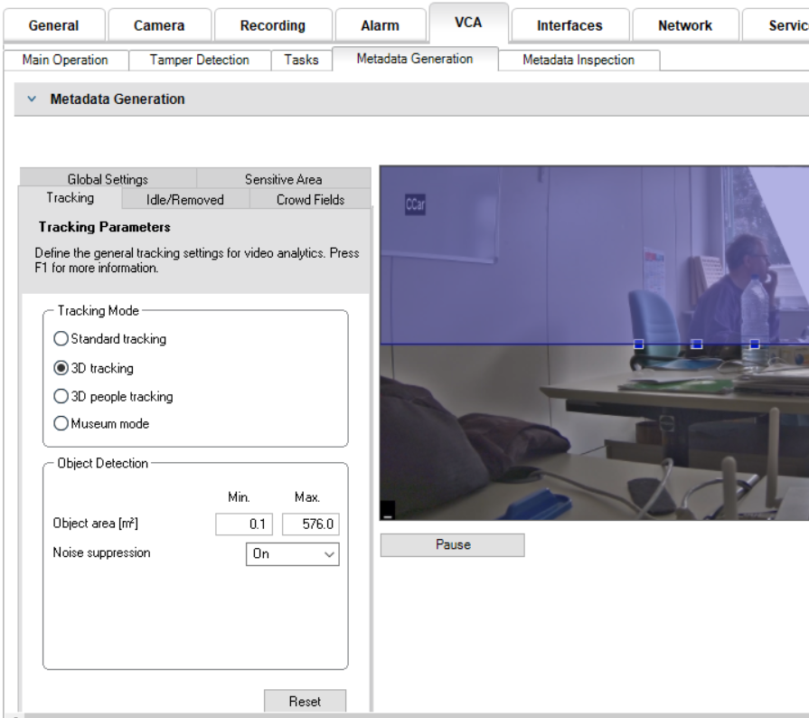
Tracking Mode setting
The VCA Task Engine handle one or more alarm condition logic, you have to go in the VCA (Video Content Analysis) tab where you can configure in the camera several tasks that could generate alarms.
Usually to generate the needed script it is sufficient to use the available wizard for the generation of one or more alarm conditions: each task configuration can be set clicking the New button.

Starting a New task configuration wizard
Each task can be set choosing one of the following logics in the Essential Video Analysis and then graphically drawing lines/areas on the stream image (for more details see Video Content VCA 6.30): Detect any object, Object in field, Crossing line, Entering field, Leaving field, Loitering, Following route, Removed object, Idle object, Counter, Entering field, Leaving field, Loitering, Following route, Removed object, Idle object, Counter, Occupancy, Crowd detection, Condition change, Similarity search.
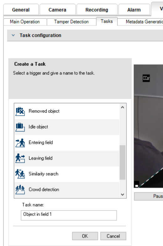
Select the needed main logic
A field can be set (drowned a new one or selected, if already available), for example, in a Entering field VCA logic. There are several object triggers available (i.e. Object base point, Object center, Edge of box, Complete box). If you want to generate an alarm as soon as an identified object enter in the selected area, even only with an edge of the box, you have to set, for the Entering field task, an Interaction trigger as Edge of box. The same if you want to have an alarm only if the whole object has completely left that area. In fact, the logic for configuring a Leaving field task is dual respect the one for Entering field, that the object trigger Edge of box generates an alarm event if no edge of the object is any longer within the field and thus the object is completely outside the field, while the object trigger Complete box generates an alarm event as soon as any part of the virtual frame around the object is outside the field. Note: if the tasks configuration section have only a link to the web version of the tool, il means that you need to update both the Configuration Manager version and the Camera firmwaere to their latest version, as I have already undelined before.
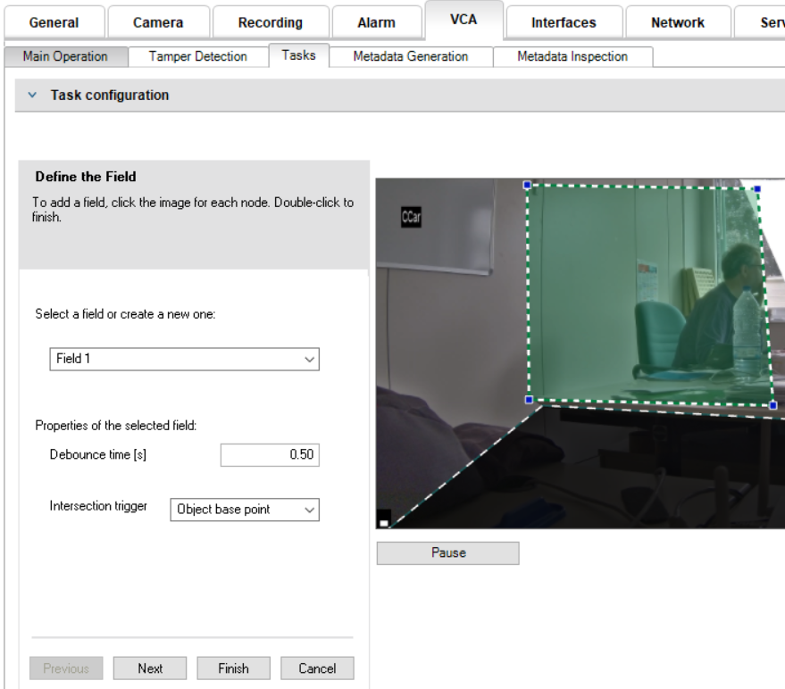
Fiend drawing/selection in a Entering field VCA logic definition
If needed, a filter on one or more available object classes can be set. Note that, as already stressed, to set an analysis on Object class, you need to properly set the Tracking me to 3D tracking or specifically to 3D people tracking if you are only interested to identify persons.
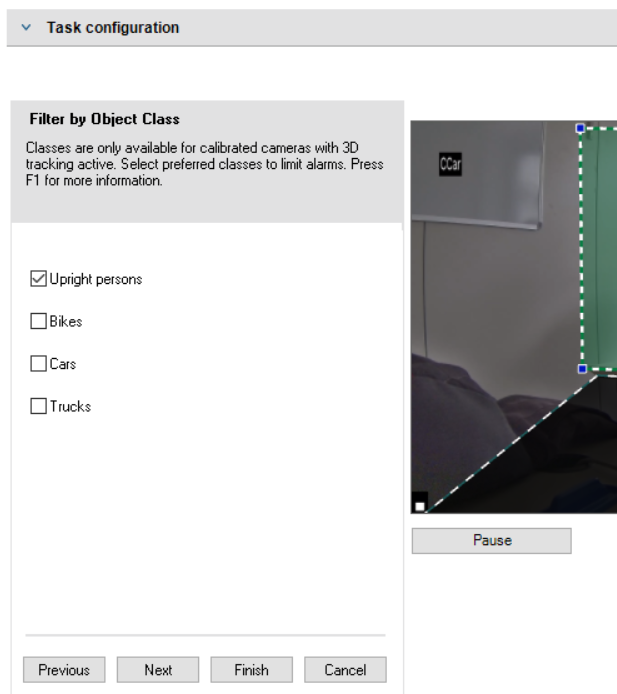
Filtering on one or more available object classes
The recognition of object is not performed at 100% and the percentage of successes depends on many factors, first of all the camera location (top down views require a camera height of more than 3 meters. A camera height of more than 4 meters offers the best results); moreover moving objects like leaves of plants could cause false alarms so it is better to set a proper VCA masking as explained above.
It is important also to foresee that the zone identified for the alarm covers an area of the scene such as to exclude a sufficiently wide part to contain the object to be recognized (i.e. an upright person): so the VCA SW is able to identify it before he enters in the alarm zone and therefore activate the programmed task.
You can also filter detected object on the basis not only of and Object classes but also of Duration, Size, Aspect ratio v/h, Speed, Direction and even a Color.
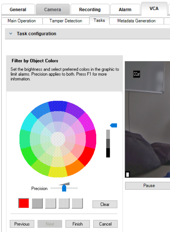
Color filter definition
In the case you set a task with a Crossing line logic, you can draw a line (even a polyline) and set a direction.
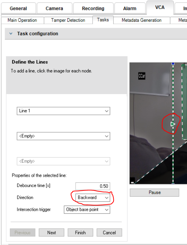
Line (or even polyline) draw in Crossing line logic
In the following there is an example of three task setting, the first two of them set active for alarm.

Three Tasks definition example (two set to generate alarm)
To see the VCA Task Script generated with the wizard, you have to right click on the stream and chose Advanced -> VCA Task Editor.
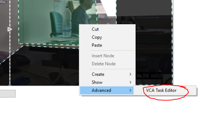
VCA Task Editor
An example of generated VCA Task Script , generated with the wizard, is the following (note that Event#3 is commented – C# notation – because that Task is now not set to generate an alarm) :
Resolution := { Min(-1, -1) Max(1, 1) }; Field #1 := { Point(-0.519, -0.967) Point(0.219, -0.944) Point(0.269, 0.289) Point(-0.513, 0.256) DebounceTime(0.50) ObjectSet(FootPoint) }; Line #1 := { Point(-0.600, -0.989) Point(-0.600, 1.000) DebounceTime(0.50) Direction(2) TriggerPoint(FootPoint) }; //@Task T:10 V:0 I:1 "Entering field 1" { //[1.a=1;1.b=1;2.a=();4.a=(c:1,p:1);7.a=c:1|;] external Event #1 := {EnteredField #1 where HasClass( Person )}; //@} //@Task T:11 V:0 I:2 "Leaving field 2" { //[1.a=1;1.b=2;4.a=(c:1,p:1);7.a=c:1|;] external Event #2 := {LeftField #1 where HasClass( Person )}; //@} //@Task T:2 V:0 I:3 "Crossing line 3" { /* //[1.a=s1:1;1.b=3;1.c=32;1.d=31;3.o=();5.a=(c:1,p:1);7.a=c:1|;] external Event#3:={CrossedLine#1 where HasClass( Person )}; */ //@}In case you need to configure a more complex logic, you can write the script by hand (or better modify one automatically generated by the wizard so you have already the drawn areas and lines position): unfortunately there are not many instructions related to the VCA Task Script language, but you can find some interesting examples in the VCA Task Script Language FW 6.3 – Technical note.
One of the VCA script examples available in the VCA Task Script Language FW 6.3 – Technical note
The Alarm Task Engine supports conditions when actions shall be triggered or states shall be set. Then, going to the Alarm tab you can set an Alarm Task Script to define how to react to an alarm condition identified by the VCA programmed on the camera as previously showed. There are several Actions with the following general syntax:
:={ [ ]};where an <identifier> begins with a lower-case phrase that can be followed by either:

- A capitalized phrase
- A lower-case phrase
- A digit
- An underscore.
The following is an example of Action, being AlarmMail the action name and mail the identifier:
AlarmMail mail:={IP(“smtp.gmail.com”)To(“myEmail@gmail.com”)Layout(Standard)Camera()From(“SendingEmail@gmail.com”)Login(“SendingEmail@gmail.com”)Password(“SendingEnmailPSW”)VCAOverlay(false)Format(256,144)Port(25)};
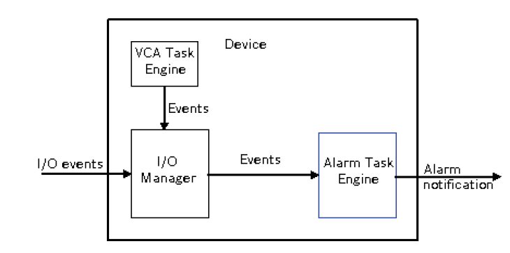
Alarm Task Engine architecture
For testing purposes you can firstly try the email action. It can be easily configured from the Alarm tab, even though the Alarm Task Editor tab allows you to possibly even better define the logic: the form allows you to configure not only Alarm e-mail, but also Alarm connections (to send a video stream) and Alarm input (that takes into account one of the external input of the camera).
The easiest one to be configured an Alarm e-mail, possibly using a Google SMTP and a Gmail account you have: note that it is better to create a dummy account, because both username and password are visible in the generated script visible from the Alarm Task Editor tab (even though when you input the password in the related form it is not clearly displayed).
Moreover note that the sender address input is mandatory and you can find the that Mail server IP address and port for example here or looking to the following screenshot.
BE CAREFUL to set to On the Send alarm e-mail (first combo in the Alarm e-mail section of the form) and click on another main section other than Alarm – e.g. General or Camera – to have the input you inserted saved and have the Alarm Task Script generated automatically. If you want that the email contains attached also the image taken when the alarm is generated, you have to check the Attach JPEG from camera and possibly set VCA Overlays if you want it shows also the overlays (e.g. lines around recognized objects).
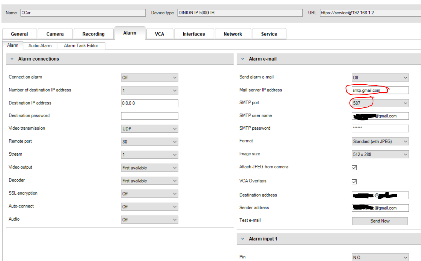
Configuring an alarm email using Gmail SMPT
The automatically generated Alarm Task Script is the following:
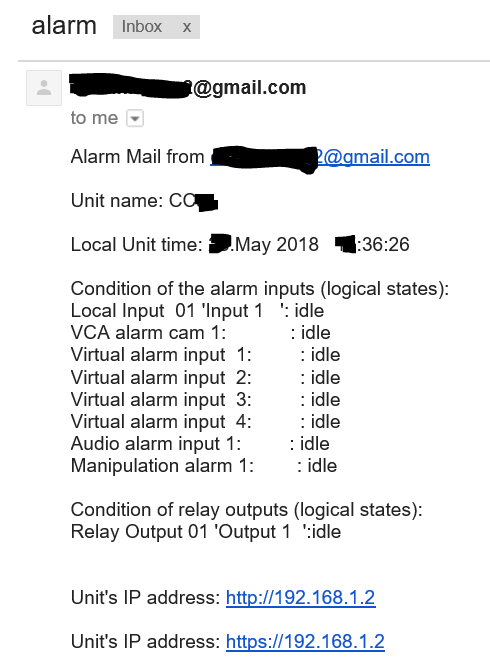
//{{email_start AlarmMail mail:={IP("smtp.google.com")To("myEmail@gmail.com")Layout(Standard)Camera(1)From("SenderEmail@gmail.com")Login("SenderEmail@gmail.com")Password("SenderEmailPSW")VCAOverlay(true)Format(256,144)Port(587)}; //}}email_end c8630e470b3f4345ee60e7e24b0615c9You can then test the correctness of your inputs using the Send Now button, that simulate an alarm event and should generate a new email in the inbox.
E-email sent after an alarm condition detected by the VCA
If you go in the Alarm Task Editor tab, you can see the following generated Alarm Task Script that, in that case, includes the definition of an AlarmMail object that is then used whenever some alarm task conditions are detected by the camera, on the basis of the VCA Task Script generated/written in the VCA tab, as previously shown, being 1 the camera number:
//{{email_start AlarmMail mail:={IP("smtp.gmail.com")To("myEmail@gmail.com")Layout(Standard)Camera()From("SenderEmail@gmail.com")Login("SenderEmail@gmail.com")Password("SenderEmailPSW")VCAOverlay(false)Format(256,144)Port(25)}; if(Motion(1)) then mail; ... //}}email_end 817e3425d01db79a6a7e4f8f99662dc3Note that, as already stressed, the sending e-mail password is visible in the generated script available from the Alarm Task Editor tab (even though when you input the password in the related form it is not clearly displayed), so it is better to use not a personal account but a service specific or a dummy one.
Related to Alarm Task Script Language, to be used to react to an alarm condition detected by the VCA using the Alarm Task Script, there are the following documents:
You can be interested also in these links related to IVA (Intelligent Video Analysis) but only in case you want to do very specific topics:
- Intelligent Video Analysis: IVA Task Script Language (Version 1.2)
- VideoSDK 6.14 (see Video SDK: IVA events (Line crossing) and SDK video tutorials — RCP+: IVA events (Line crossing) where it is shown how it is possible to write C# code to integrate logic with Video SDK or RCP+ over CGI.
However technical documents related to the camera are not exhaustive and, in my opinion, they lack of practical examples. A little help can came from watching Bosch tutorials on YouTube that can be mainly found in https://www.youtube.com/user/BoschSecurity:
-
- Intelligent Video Analysis: intelligent traffic application
- Bosch Intelligent Video Analysis (IVA): Bosch Intelligent Video Analysis (IVA) helps operators stay focused by introducing a new level of automation to CCTV monitoring. Edge-based, real-time processing identifies alert conditions, giving your security team the information, it needs to react swiftly and take
- Bosch Intelligent Video Analytics (IVA) – counting, loitering, removed object: Demo video showing Bosch Intelligent Video Analytics (IVA). The video show people counting, loitering alarm and removed object alarm.
- Assisted Self Calibration
- RCP+: Change video profile : how to change video profiles using RCP+ over CGI (Computer Graphics Interface). This feature enables you to set different video profiles by changing for example the resolution and assigning it to a specific video stream.
- Bosch IP camera configuration — Storing on SD card : how to store video on the SD card in a Bosch IP camera.
- Bosch IP camera configuration — Motion detection: how to configure motion detection in a Bosch IP camera.
- Bosch IP camera configuration — Tamper alarm: how to set up a tamper alarm in a Bosch IP camera.
- Bosch IP camera configuration — Audio Alarm: how to configure a Bosch IP camera for audio alarming.
- IP camera configuration — Privacy masking: how to configure privacy masking in a Bosch IP camera.
- Bosch IP camera configuration — Motion alarm: how to configure a Bosch IP camera for motion alarming.
- Bosch IP camera configuration — Motion alarm: how to configure a Bosch IP camera for motion alarming.
- Bosch IP camera configuration — Dropbox setup: how to configure a dropbox account for a Bosch IP camera.
- Video SDK: IVA events (Line crossing): how to implement Intelligent Video Analysis (IVA) events using the Bosch Video SDK. IVA supports your security personnel with a comprehensive and efficient alarm system and event detection, VCA like ‘line crossing’. For further tutorials and full functionality (download of code snippets & commands) please visit us at: http://ipp.boschsecurity.com/en/techn…
- Bosch Security – Enforcing no-parking zones with Essential Video Analytics: It can be used for advanced intrusion detection (such as loitering alarms and identifying a person or object entering a pre-defined field), enforcing health and safety regulations such as no-parking zones, detecting blocked emergency exits or objects that have been left behind, and analyzing behavior in retail environments.
========================
If you want to send a custom message when one of the alarms occurs, as defined with the VCA Task Script Language, you have to use the HttpCommand Action that allows you to send HTTP commands to another device (or even to the device itself, as localhost).
The <http command> can be any kind of HTTP command which shall be sent to an HTTP server using GET/.
The following is the given as an example:
HttpCommand sendHttp:={ Command("HttpSrv.aspx?command=httpCommand1")SSL(true) Port(HTTPS)IP("192.168.0.1") Password("anonymous")UserName(User)Name("Http Command 1")};As an example of Alarm Task Script, if you want to send both a mail and a http get, is the following when every time one of the two VCA Task event occurs::
//{{email_start AlarmMail mail:={IP("smtp.gmail.com")To("MyGmail.com")Layout(Standard)Camera()From("SenderEmail@gmail.com")Login("SenderEmail@gmail.com")Password("SenderPWD")VCAOverlay(false)Format(256,144)Port(25)}; HttpCommand sendHttpPedestrian := {Command("r/1601qm31?command=ped&amp;amp;amp;enter=true")SSL(false)Port(HTTP)IP("requestbin.net")Name("Http PEDESTRIAN")}; HttpCommand sendHttpCar := {Command("r/1601qm31?command=car&amp;amp;amp;color=red")SSL(false)Port(HTTP)IP("requestbin.net")Name("Http CAR")}; if(VCARule(1,1)) then sendHttpPedestrian; if(VCARule(1,1)) then mail; if(VCARule(1,2)) then sendHttpCar; if(VCARule(1,2)) then mail; //}}email_end 817e3425d01db79a6a7e4f8f99662dc3being:
- 1 the camera number (set as first parameter of VCARule)
- 1 the VCA Task event related to detecting the presence of a pedestrian in an area (set as second parameter of VCARule)
- 2 the VCA Task event related to detecting the presence of a car in an area (set as second parameter of VCARule)
============================================================
Useful site for HTTP Requests inspection
For testing purpose, a server to inspect HTTP Request can be created with the requestbin.net site: the requestbin.net/r/1601qm31 URL was created as my test server.
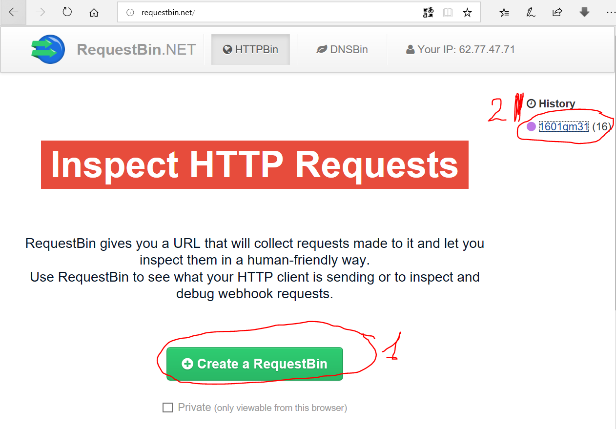
requestbin.net site to create a temporary HTTP server
Clicking on the History link, on the top right of that site, you can see all received HTTP Requests (e.g. GET, POST), as shown in the following screenshot (or you can directly go to https://requestbin.net/r/1601qm31?inspect, being the requestbin.net/r/1601qm31 your created URL):
 The URL created by requestbin.net site could be previously tested, just in case, using PowerShell, with a wget command as follows:
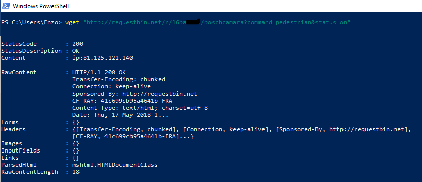
Sending a HTTP GET to requestbin server
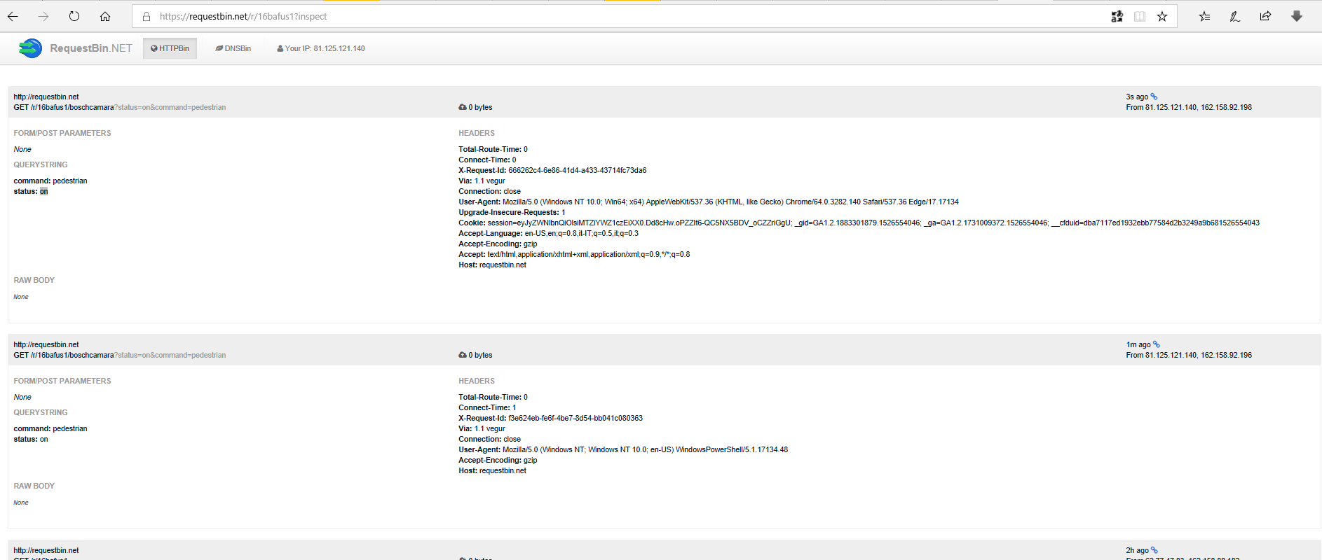
Here is the displayed IP on the requestbin.net/xxx server site:
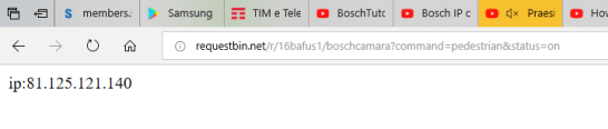
Verification that the HTTP GET is arrived to the temporary requestbin server
For a HTTP WebSocket echo server you can use http://www.websocket.org
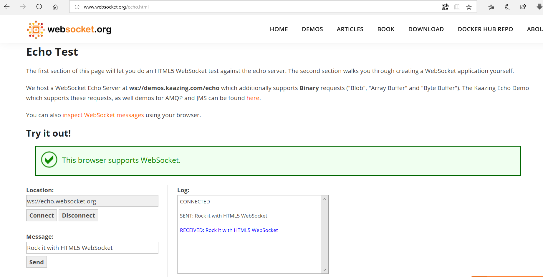
HTTP WebSocket echo server (http://www.websocket.org)
============================================================
Useful links for ASN1 specification and JSON validation
https://asn1.io/asn1playground
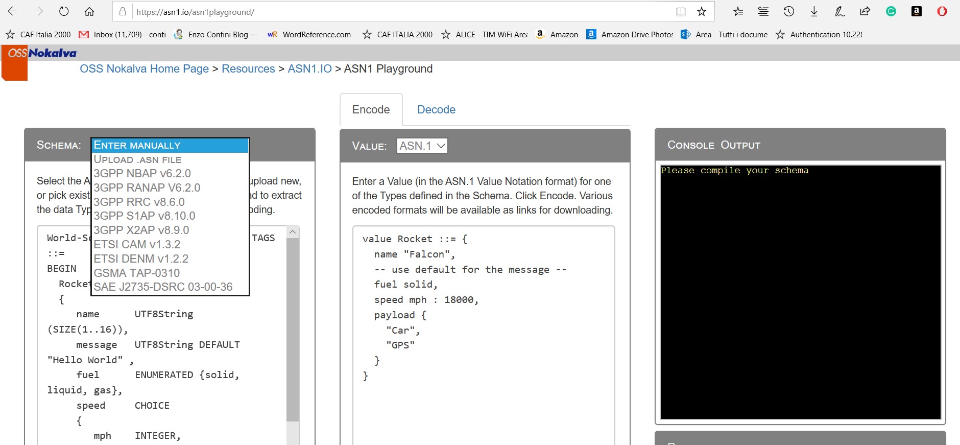
- Validate ASN1 messages for a defined schema (e.g. ITS DENM): http://asn1-playground.oss.com/
1- Select the Schema of interest from the available in the combo(e.g. ITS DENM v.1.2.2)
2- Press Compile button
3 – Past the code you want to validate with the previously chosen schema and press the Encode button
4 – Compile output that could stress possible syntax errors

Validate ASN1 messages for a defined schema (e.g. ITS DENM): http://asn1-playground.oss.com

Jsonlint – JSON validator


Pingback: Ezviz C3X: telecamera di sicurezza (anche da esterno) con rilevamento persona/auto e con molteplici interessanti funzionalità! | Enzo Contini Blog
Pingback: TObike riparte: era ora!!! :-) | Enzo Contini Blog
Pingback: La NON soluzione agli ingorghi della rotonda di p.za Baldissera a Torino (… ed i semafori NON intelligenti di p.za Derna) | Enzo Contini Blog